")
It is a common practice that a DB architect has to design a relational database tailored to a particular solution.
One Friday evening, I was coming home from work on a commuter train, and I was thinking of creating a kind of recruitment service. As I know that none of the existing services allows quick evaluation of a candidate, creation of intricate filters on certain skills, projects, or positions, or exclusion of certain skills, positions, or projects. The maximum range of use is filtering by companies and partially by skills.
In this series of articles, I will indulge myself a little bit with some non-technical examples from my life in an attempt to break rigorous technical writing.
In this part, I will write about the basics of relational database design and illustrate MS SQL Server database design for a recruitment service.
Now, as for the articles that will follow, there, I will show you how to populate a database with data by means of Data Generator for SQL Server, and search for database data and objects with the free dbForge Search tool. I will use dbForge Studio for SQL Server to implement charts for my examples, and dbForge Data Pump to import and export data.
Contents
- The Basics of DB design
- Designing a database schema for recruitment
- How to define a table structure
- Conclusion
The Basics of DB design
To design database schemas, let us recall 7 normal forms and the very concepts of normalization and denormalization. They underlie all design rules.
Let me give a detailed description of 7 normal forms:
1. A one-to-one relationship
1.1 A mandatory relationship:
An example would be a citizen with a passport (every citizen must have a passport, and a passport is one for every citizen)
This relationship is implemented in two ways:
1.1.1 In one entity (table):
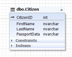
Img.1. The ‘Citizen’ entity
Here, the Citizen table represents the citizen entity, and the PassportData attribute (field) contains all passport data of a citizen and cannot be empty (NOT NULL)
1.1.2. In two different entities (tables):
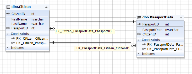
Img.2. The relationship between the Citizen and PassportData entities
The Citizen table represents the citizen entity, and the PassportData table represents the entity of the citizen’s passport data. The citizen entity contains the PassportID attribute (field) that refers to the primary key of the PassportData table. Whereas, the passport data entity has the CitizenID attribute (field) that refers to the CitizenID primary key of the Citizen table.
It is also important to guarantee the integrity of both the CitizenID field and the PassportData table, to provide a one-to-one relationship. That is, the PassportID field in the Citizen table and the CitizenID field in the PassportData table must refer to the same record as if it were one entity (table) that was illustrated in paragraph 1.1.1.
1.2 An optional relationship:
An example here would be a person who can have passport data and may not have a specified country. So, in the first case, he is a citizen of a given country, and in the second case, he is not.
This relationship is implemented in two ways:
1.2.1 In one entity (table):
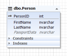
Img.3. The Person entity
Here, the Person table represents the person entity, and the PassportData attribute (field) contains all passport data of a person and can be empty (NULL)
1.2.2 In two entities (tables):
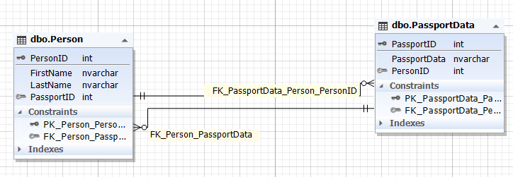
Img.4. The relationship between Person and PassportData
Here, the Person table represents the person entity, and the PassportData table represents the person’s passport data entity (that is the passport itself). The person entity contains the PassportID attribute (field) that refers to the primary key of the PassportData table. Whereas, the passport data entity has the PersonID attribute (field) in the Person table. The PassportID field of the Person table can be empty (NULL).
It is also important to guarantee the integrity of both the PersonID field and the PassportData table, to provide a one-to-one relationship. That is, the PassportID field of the Person table and the PersonID field of the PassportData table must refer to the same records as if it were one entity (table) shown in paragraph 1.2.1, or these fields must be unspecified, that is, contain NULL.
2. A one-to-many relationship
2.1 A mandatory relationship:
An illustration of this can be a parent and their children. Every parent has at least one child.
You can implement this relationship in two ways:
2.1.1 In one entity (table):
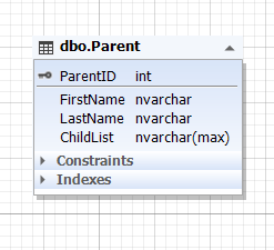
Img.5. The Parent entity
Here, the Parent table represents the parent entity, and the ChildList attribute (field) contains information about children, that is, children themselves. This field cannot be empty (NOT NULL). The ChildList field type is usually semi-structured data (NoSQL) such as XML, JSON, and so on.
2.1.2 In two entities (tables):
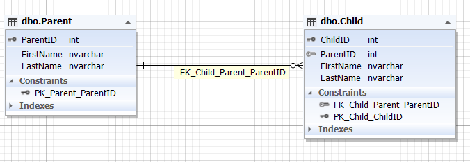
Img.6. The relationship between the Parent and Child entities
Here, the Parent table represents the parent entity, and the Child table represents the child entity. The Child table has the ParentID field that refers to the primary ParentID key of the Parent table. The ParentID field of the Child table cannot be empty (NOT NULL).
2.2) an optional relationship:
An example would be a person who might have children or might not have any children.
This relationship is implemented in two ways:
2.2.1 In one entity (table):
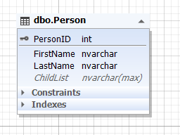
Img.7. The Person entity
Here, the Parent table represents the parent entity, and the ChildList attribute (field) contains information about children, that is children themselves. This field can be empty (NULL). The usual ChildList field type is semi-structured data (NoSQL) such as XML, JSON, and others.
2.2.2 In two entities (tables):
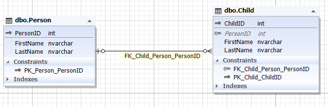
Img.8. The relationship between the Person and Child entities
Here, the Parent table represents the parent entity, and the Child table represents the child entity. The Child table has the ParentID field that refers to the primary ParentID key of the Parent table. The ParentID field of the Child table can be empty (NULL).
Also, there is a third way of one-entity implementation that refers to itself, on the condition that the child and the parent entities (tables) have the same set of attributes (fields) without a reference to parent:
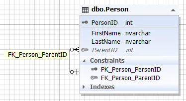
Img.9. The Person entity with a self-reference
Here, the Person entity (table) contains the ParentID attribute (field) that refers to the primary PersonID key of the same table Person and can have an empty value (NULL).
This is the implementation of a many-to-one relationship with an optional nature.
3. A many-to-one relationship
This relationship mirrors the illustrated above one-to-many relationship. That is the relationship between the child entity and the parent entity, where the mandatory relationship is possible if the child has at least one parent, and if we take all children, including those in orphan houses, then such a relationship has optional nature.
A one-to-many and many-to-one relationships can also be implemented through more than 2 entities, by adding the necessary attributes that refer to the primary keys of the corresponding entities. This implementation is similar to the examples above in paragraphs 1.1.2 and 1.2.2.
4. A many-to-many relationship
In this case, an example would be real estate that can be owned by one person or several people. At the same time, a person can own several houses or have an ownership share of many houses.
You can implement this relationship with NoSQL in the ways described above for the previous relationships. However, within the relational model, this relationship is normally implemented through 3 entities (tables):
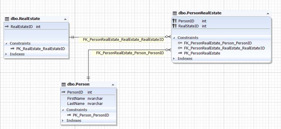
Img.10. The relationship between the Person and RealEstate entities
Here, the Person and RealEstate tables represent the entities of a person and real estate accordingly. These entities (tables) are related by means of the PersonRealEstate entity (table) through the PersonID and RealEstateID attributes (fields) that refer to the primary keys PersonID of the Person table and RealEstateID of the RealEstate table correspondingly. Note that the pair (PersonID; RealEstateID) is always unique for the PersonRealEstate table, thus it can be the primary key for the very PersonRealEstate linking entity (table).
This relationship can be implemented through more than 3 entities by means of adding the necessary attributes that refer to the primary keys of the corresponding entities. Such an implementation is similar to the examples described in paragraphs 1.1.2 and 1.2.2.
So where are the 7 normal forms, you may wonder?
Well, here they are:
- Par.1 (par.1.1 and par.1.2) is the first and the second formal rule.
- Par.2 (par.2.1 and par.2.2) is the third and the fourth formal rule.
- Par.3 (similar to par.2) is the fifth and the sixth formal rule.
- Par.4 is the seventh formal rule.
It is just that these 7 normal forms are grouped in 4 functional blocks in the text above.
Normalization eliminates data redundancy and hence, decreases risks of data anomalies. However, normalization when decomposing entities (tables) results in a more complex query build for data manipulation (insertion, update, selection, and deletion).
The opposite process is denormalization. It simplifies query processing for data access by means of adding redundant data (for instance, as it was mentioned above in par. 2.1.1 and 2.2.1 with the help of semi-structured data (NoSQL)).
Are you sure that you got the point of 7 normal forms? That you really got it and not just familiarized yourself with it. Ask yourself whether, in a couple of hours, you will manage to design a database model, even with excessive entities, for any data domain or any information system. You can polish intricacies and details later by asking analytics and customer representatives.
If this question caught you off guard, and you think accomplishing this is highly unlikely, then you know the 7 normal forms but do not understand them.
Somehow it is not stated in the sources that these relationships between entities were not just made up but discovered. That is, from the very start, they actually existed in the real world between subjects and objects.
In addition to that, these relationships can change, shifting from one-to-one to one-to-many, or to many-to-one, or to many-to-many, changing their mandatory nature or preserving it.
I think you should try watching people and detecting the existing relationship both between subjects and between subjects and objects (the example above illustrated a citizen and a passport as a one-to-one relationship with mandatory nature, and a person and a passport as a one-to-one relationship that is optional).
When you have gained insight into 7 normal forms, you can easily design a database model of any complexity for any information system.
Apart from that, you will come to know that you can implement the relationships in many different ways, and the relationships themselves can change. Thus, the database model (schema) is a snapshot of relationships between entities at a certain point in time. Hence, it is essential to specify both entities, which are images of real-world or domain objects, and relationships between them taking future changes into account.
A well-designed database model, with due regard to relationship change in reality and in the subject domain, does not require any alterations for a long time. It is especially vital for data storage where changes involve resaving big volumes of data, ranging from several gigabytes to many terabytes.
Note: in a relational database model, it is the relationship between entities, and rows (tuples) are examples of these relationships. But to make it simple, we often mean entities by tables, and instances of entities by rows, and their relationship by external keys relationship.
Designing a database schema for recruitment
After we have described DB design basics in the first part of the article, let us now create a database schema for recruitment.
First of all, we need to define which information is important for company employees who search for job applicants:
- For an hr-manager:
- Companies where an applicant used to work at.
- Positions that an applicant used to hold at these companies.
- Skills that an applicant used at work, length of their employment at each of the companies and in each position, length of each skill use.
- For a technical specialist:
- Positions that an applicant used to hold at previous places of work.
- Skills that an applicant used at work.
- Projects that an applicant took part in. In addition to that, it is important to know the applicant’s length of employment in each position and in each project as well as the length of each skill use.
Let us first identify the necessary entities:
- Employee
- Company
- Position
- Project
- Skill
Company and employee have a many-to-many relationship since an employee could work for different companies, and the companies have many employees.
The same works for position and employee, because many employees can work in one position within one company as well as in different companies. Herewith, an employee could work in different positions both within one company and at many different ones. As a result, the relationship between position and company is many-to-many as well.
The “project” entity follows the same logic: the project relates to all other above-mentioned entities as many-to-many.
For simplicity, let us say that an employee uses one set of skills in a project. Then, the relationship between project and skill is also many-to-many.
Considering the importance of specifying an employee’s length of employment at this or that company, in a particular position, and in a certain project, our database schema may have the following ER diagram:
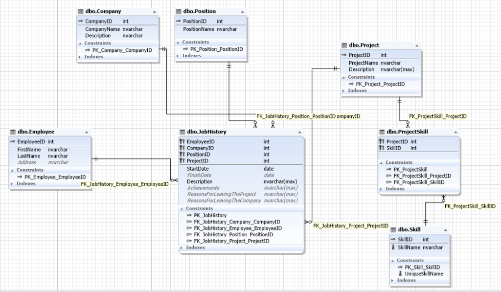
Img.11. The database schema for a recruitment service
Here, the JobHistory table represents the entity of each employee’s job history, that is, the very resume that implements the many-to-many relationship between employee, company, positions, and project.
Project and skill relate as many-to-many, thus, they are linked with the help of the ProjectSkill entity.
If you understand the relationship between subjects, and subjects and objects, meaning database design norms, you can create a similar schema on a piece of paper in under an hour.
Here, we could simplify the schema and data addition, if we put skill in the project entity through semi-structured data (NoSQL) in the form of XML, JSON, or simply list the names of skills with a semicolon. But this would make it difficult to select grouping by skills and filter by certain skills.
How to define a table structure
A table contains columns and indexes. Besides, a table has options such as table type, row format, and so on. Defining a table structure means setting up all these elements.
To define table structure, create a table or open an existing one from Database Explorer. There are five tabs in Table Editor: Main, Constraints, Indexes, Storage, and Data.
Defining columns
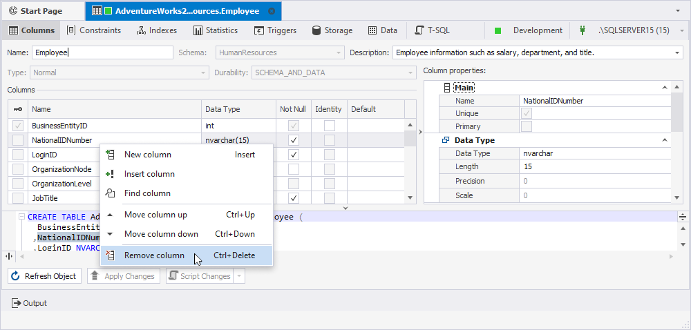
Switch to the Columns tab of Table Editor to define columns or rename the table.
To add a column to the table, right-click the grid, and then click New column in the shortcut menu. Alternatively, press the INSERT key.
To edit an existing column and its properties, double-click a column row.
To remove a column, right-click it and select Remove column from the shortcut menu.
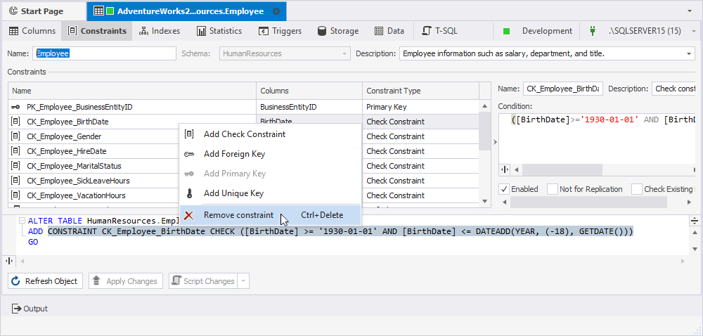
Defining constraints
Switch to the Constraints tab of Table Editor to add or alter foreign and primary keys.
To add a key to the table, right-click the tab, and then click Add Foreign Key or Add Primary Key in the shortcut menu, then choose the type of key you want to create.
To edit an existing key, double-click its row.
To remove a key, right-click it and select Remove constraint from the shortcut menu.
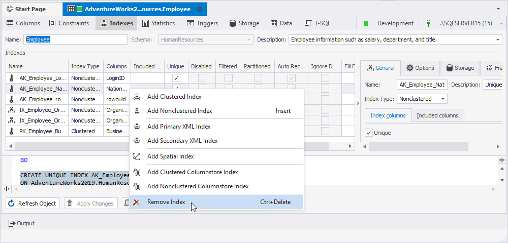
Defining indexes
Switch to the Indexes tab of Table Editor to define indexes. Generally, it is similar to defining columns.
To add an index to the table, right-click the tab and choose the required index type from the shortcut menu. Another way to do it is to press the INSERT key.
To edit an existing index and its properties, double-click an index row to accomplish this task.
To remove an index, right-click it, and then click Remove Index in the shortcut menu.
Conclusion
As you can see, designing systems is just turning objects and subjects from reality to database entities where the relationship between these entities is fixed at a certain time point, taking future changes into account. What exactly we take from reality and implement as a schema entity, and what kind of relationship we build in a model, depends on what we want from an information system in general, now and in the future. That is, which data we want to obtain for the present moment and in some time in the future. The next part will be about populating the resulting database with data. To fill our database with data, we are going to use dbForge for SQL Server.