")
Entity Relationship Diagrams are widely used for analyzing database structure and troubleshooting issues with logic or deployment. In this article, we provide a detailed walkthrough of what an ER Diagram is and how to create and manage database diagrams.
Contents
- What is Entity Relationship Diagram (ERD)?
- Create a new database diagram using SSMS
- Create a new database diagram using SQL Designer
- Create and edit database objects on a database diagram
- Tune the design of a database diagram
- Export SQL relationship diagram
- Features of dbForge Database Diagram Designer
What is Entity Relationship Diagram (ERD)?
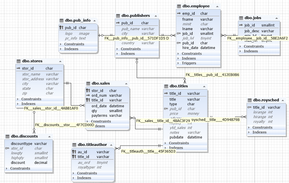
Entity Relationship Diagram comprises a graphical representation of database structure and relationships between database objects. In other words, an ER diagram is used to sketch out the design of a database and illustrate its structure.
ER Diagrams vs. ER Models
ER Model is short for entity-relationship model, which is a high-level data model. It consists of a collection of entities (or objects) and their relationships. The terms ER Model and ER Diagram are sometimes used interchangeably. However, many experts prefer to separate them, emphasizing the conceptual nature of ER Model that describes the structure of data and doesn’t explain how exactly it is stored. ER Models deal with single entities like a Customer while ER Diagrams deal with sets of entities like the Customers table.
How ER Diagrams are used
Design databases
When working on a new data model, a database diagram can help capture and document system requirements. In speaking of the existing databases, Entity Relationship Diagrams can explain the logical structure and the flow of information within the databases in question, as well as assist in enhancing database throughput, debugging errors, and redesigning the architecture.
Troubleshoot and monitor databases
The use of ER Diagrams is also beneficial when it comes to locating and resolving issues with logic and deployment. Diagrams outline the structure of a database and help understand what and where goes wrong. ERD streamlines business processes by identifying redundancies and bottlenecks within business entities.
Manage business information systems
ER Diagrams are used extensively for analyzing and fine-tuning relational databases that are commonly exploited in business processes. Entity Relationship Diagrams can help understand how those databases can be restructured for data to be retrieved quicker and easier.
This list of uses of Entity Relationship Diagrams is not at all exclusive. Database diagrams are also used in business processes reengineering, education, data analysis, and research.
Symbols commonly used in ER diagrams
Before we proceed to create ER diagrams, let’s ensure we understand the basic meaning of symbols, components, and relationships so we can read them clearly. Typically, an ER diagram consists of:
- Rectangles, which represent versatile entity types. Note that entities, that depend on another entity, are called “weak entities” and are often displayed as double rectangles.
Ellipses, which stand for attributes that showcase the properties of an entity.
There are several variations of attributes you might need to display:
- Key attributes, which are displayed as ellipses that have an underlined text within and showcase a unique identifier of an entity from an entity set.
- Composite attributes, which consist of several other attributes, and are often showcased as an oval connected with other ovals.
- Multivalued attributes, which have more than one value and are displayed as a double oval.
- Derived attributes, which derive from other attributes of an entity, and are shown as ovals that have a dashed outline.
- Diamonds, which can be used to showcase types of relationships.
- Lines, which are often used to link attributes to entity types with other relationship types.
- One-to-one relationships, that are depicted as a diamond shape between two entities, symbolizing that only one entity is related to the one to which it’s connected.
- One-to-many relationships, which are shown as a diamond shape that specifies a connection for many entities that logically might be connected only to one entity.
- Many-to-one relationships, which are used when more than one entity value can be connected with only one entity.
- Many-to-many relationships, used to connect entities that can have many values with entities similar to them.
- Create and edit tables
- Edit and manipulate (filter, group, sort, search) table data
- Modify column collations
- Create and/or remove CHECK constraints, define conditions for them
- Add and/or remove unique, primary, and foreign keys
- Permit or restrict values that can be applied to a column
- Add and/or remove unique and non-unique indexes
- Define index types: Clustered, XML, Clustered/Nonclustered Columnstore, or Spatial
- Create and manage statistics
- Create and update triggers
- Define storage properties
- Edit table creation scripts
- Right-click the diagram and select Export to Image from the shortcut menu.
- Specify the target file name and image format.
- Click the Save button.
- Export the diagram to the vector format (emf).
- Use third-party RAM defragmentation and application optimization tools.
- Try to restart the application and export the diagram again.
- Information Engineering (IE)
- IDEF1 Extended (IDEF1X)
- Allow you to visualize logical relations between tables
- Do not exist physically and are only stored on the diagram
- Can be used to simplify the visual analysis of the data
- Can be materialized further into a physical relation
- Edit the existing virtual relations
- Generate a schema script taking into account selected virtual relations, edit the script, and execute it to update a database
- Convert a virtual relation into a foreign key
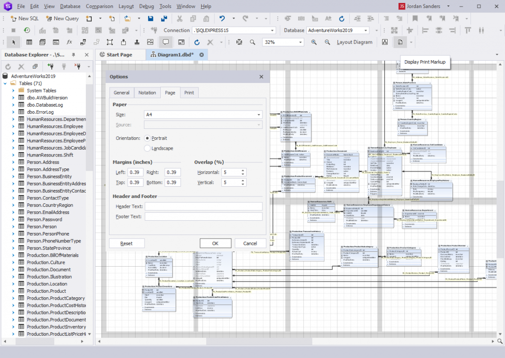
- Page orientation
- Paper size and source
- Printing margins and overlapping
- Header and footer text
- Position a printed image in the center
- Adjust diagram scale
- Set up printing of the page markup that helps to cut and glue together a SQL diagram printed on several sheets
- Edit a foreign key using the foreign key editor
- Find a foreign key in Database Explorer
- Synchronize with document outline window
- Reroute a relation
- Show a relation comment
- BMP
- JPEG
- TIFF
- PNG
- ICO
- EMF
- WMF
ER diagram relationships
Apart from symbols, it’s also essential to know how to read relationships used in a diagram. Overall, there are four main relationship types you can use:
Create a new database diagram using SSMS
SQL Server Management Studio—an integrated environment for managing SQL Server databases—allows creating database design diagrams in a couple of clicks.
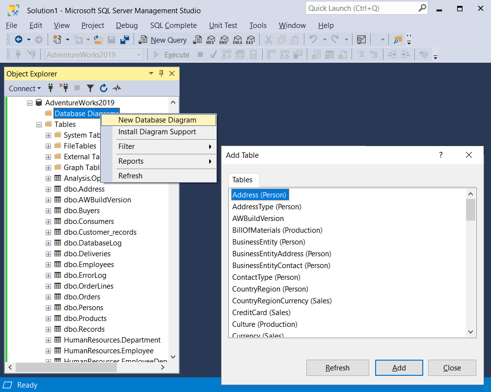
To create a database diagram in SSMS:
1. Go to Object Explorer and expand the database node.
2. Right-click the Database Diagram folder and select New Database Diagram.
Note
If the database does not have the objects necessary to create diagrams, the following message appears: This database does not have one or more of the support objects required to use database diagramming. Do you wish to create them? Click Yes.
3. In the Add Table dialog that appears, select the tables to be displayed on the diagram and click Add.
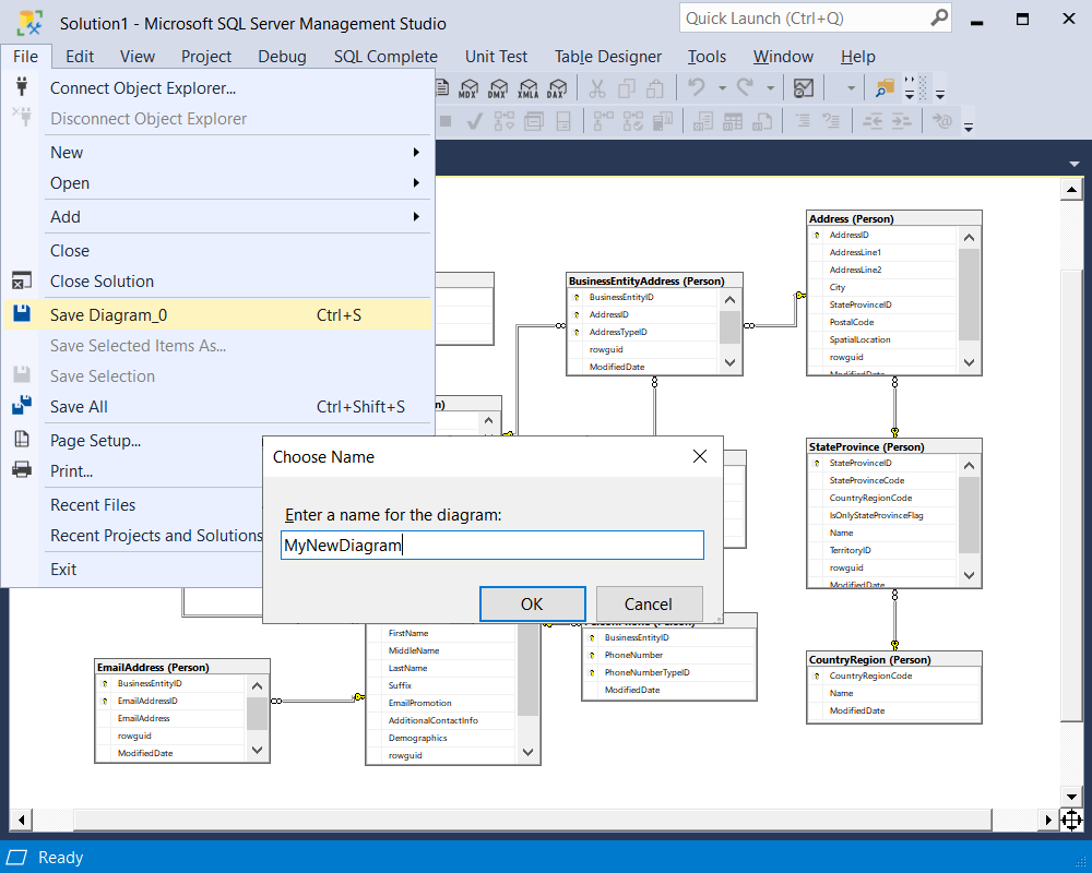
4. Optional: Arrange the tables on the diagram as required.
5. To save the diagram, go to the File menu, select Save Diagram, and provide a name for the new diagram in the Choose Name dialog that appears. Then click OK.
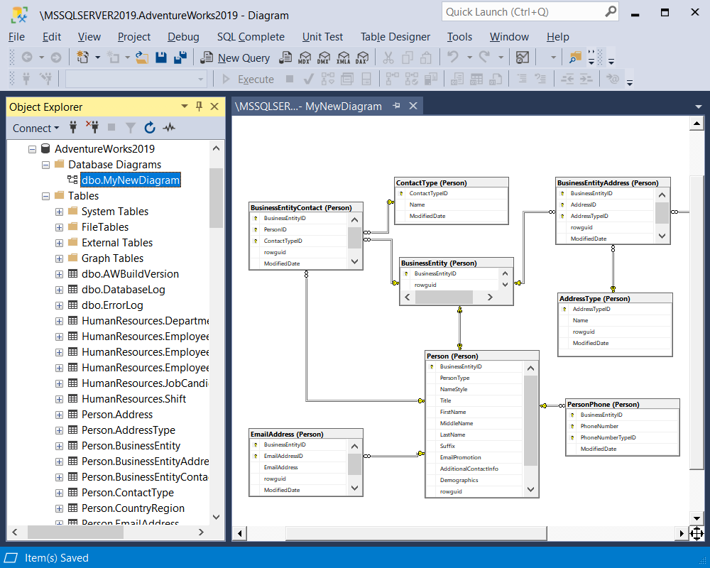
6. Once your diagram is saved, you will be able to find it under the Database Diagram folder.
Create a new database diagram using SQL Designer
There is a bunch of decent diagramming tools for SQL Server databases on the market. The one that really stands out is dbForge Studio for SQL Server—an all-embracing IDE for all possible SQL Server database-related tasks. The Studio boasts a powerful SQL Designer aimed at covering the needs of developers, DBAs, data and business analysts. SQL Designer embraces a number of utilities for creating and editing databases, designing tables, building database relationships, etc.
Its robust ER diagram tool allows designing database diagrams and visualizing database structures as Entity Relationship Diagrams.
SSMS Diagram tool vs. dbForge Studio’s SQL Designer
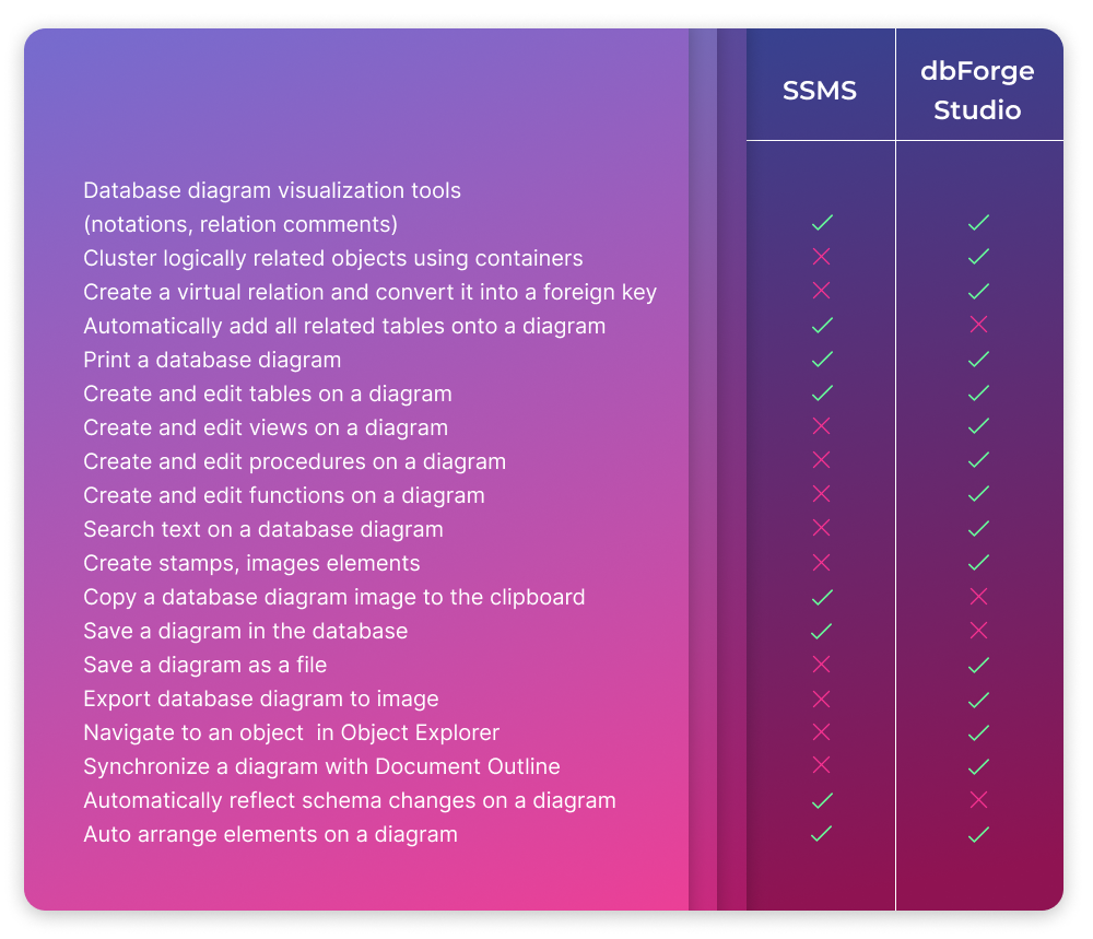
Interested in how dbForge Studio for SQL compares to SQL Tools? Learn more about the key differences.
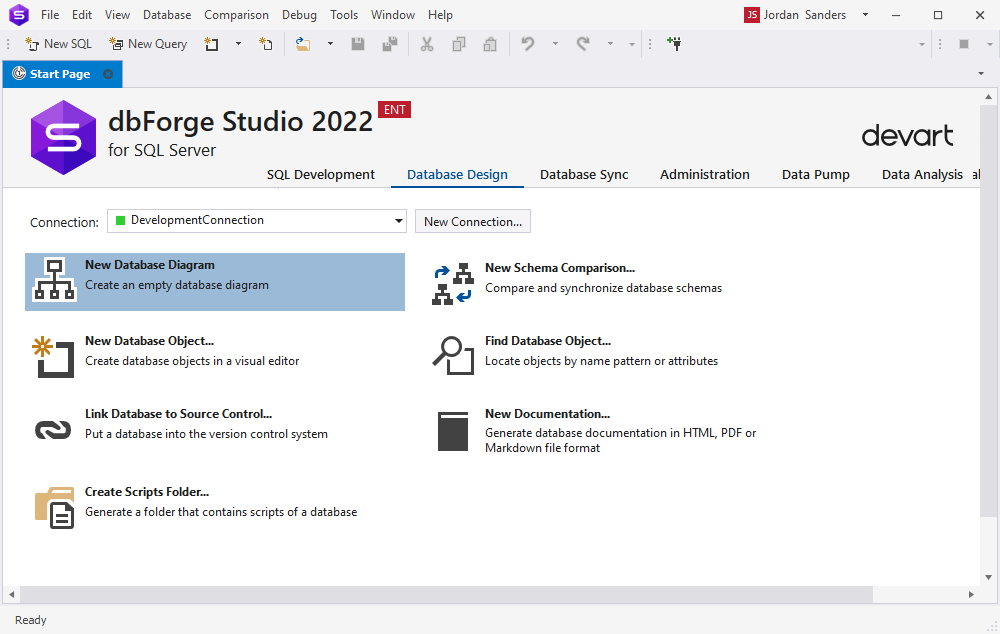
How to create a database diagram in dbForge Studio for SQL Server
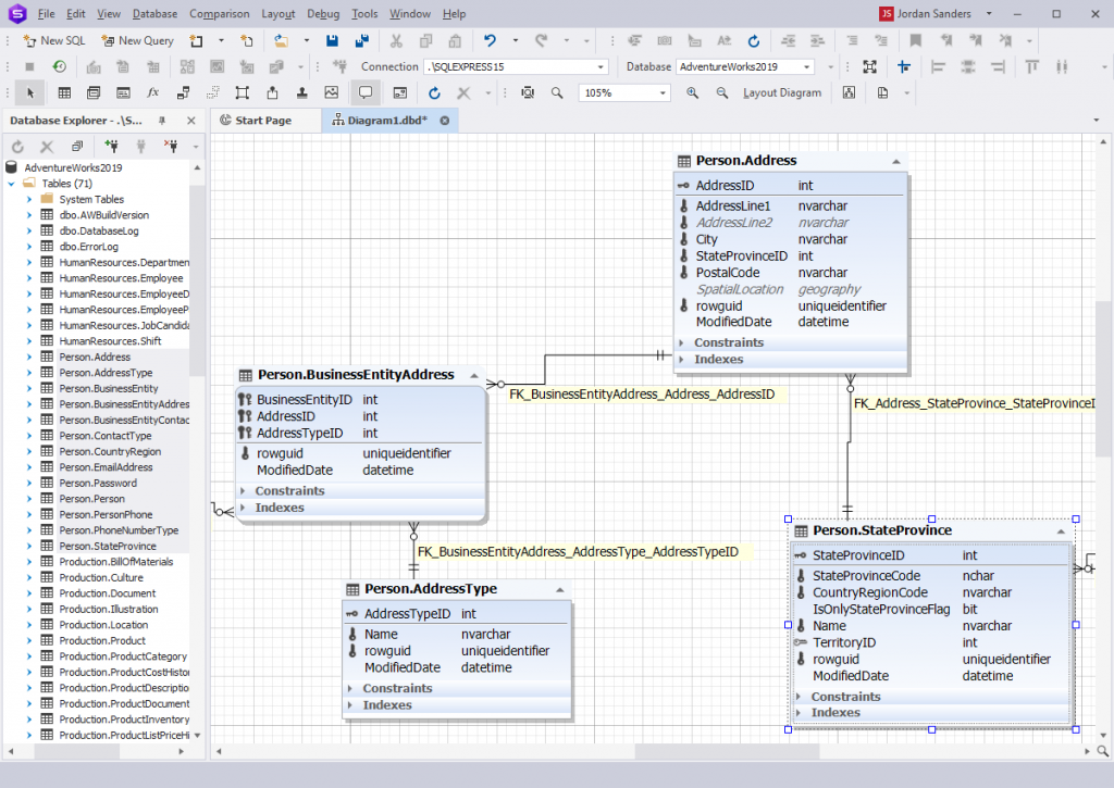
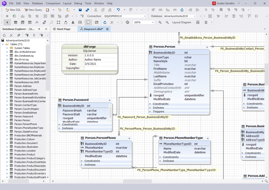
In dbForge Studio, you can create a database diagram right from the Start Page. Navigate to the Database Design tab and click New Database Diagram.
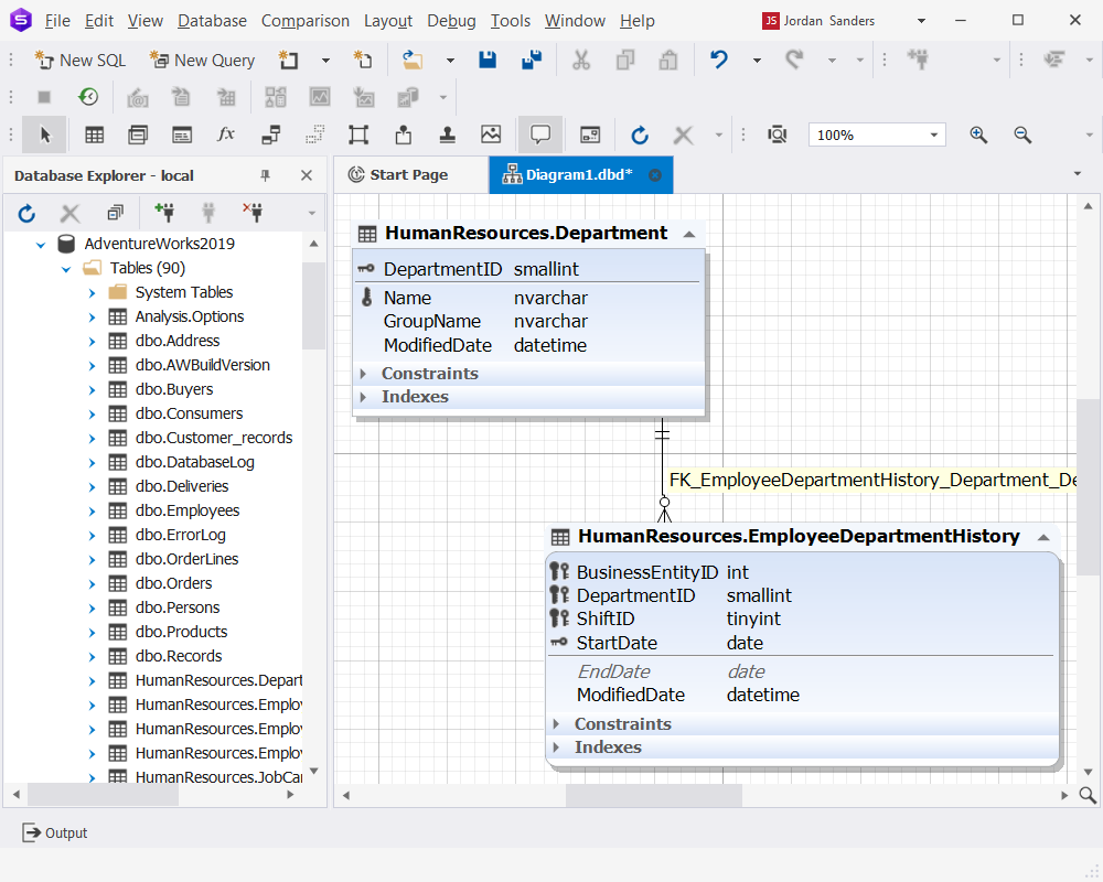
Then drag and drop database objects from Database Explorer onto the ER diagram. The database diagram will instantly display the objects and their relationships, thus facilitating further analysis.
To save a diagram:
Right-click the diagram background and select Export to Image from the context menu.
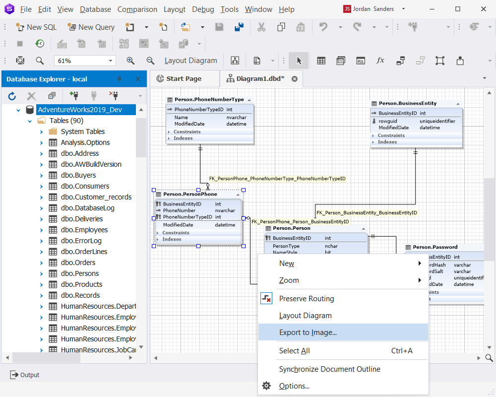
You can save the diagram in the following formats: BMP, JPG, GIF, PNG, TIF, and EMF.
Create and edit database objects on a database diagram
You can visually design databases by creating and modifying database diagrams. Well-designed databases are easy to manage and maintain, they boast improved data consistency and are cost-effective in terms of disk storage space.
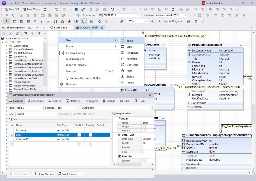
Create a new database object on the diagram
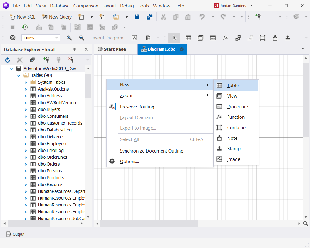
To create a new database object, right-click the database background, select New from the context menu that appears, and then select the type of database object you want to create: Table, View, Procedure, or Function. The corresponding database object editor will open.
With dbForge Studio for SQL Server, you can also visually create a new foreign key relationship between two tables.
Curious about more ways to design a database without code? Learn about database design and modeling tools that will handle this task!
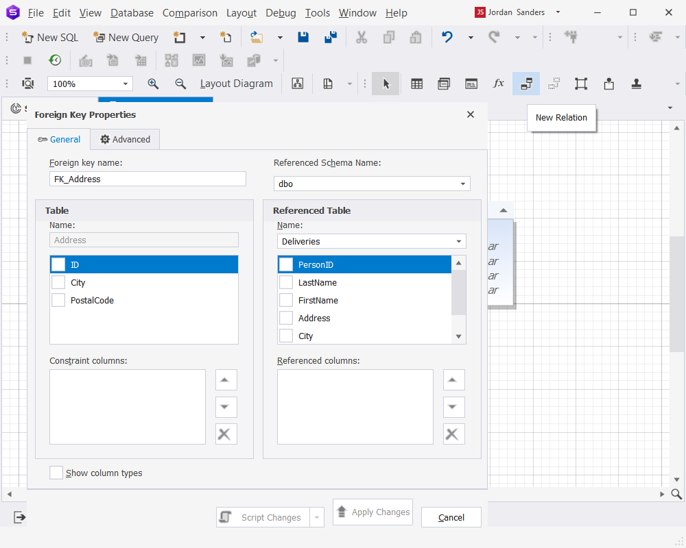
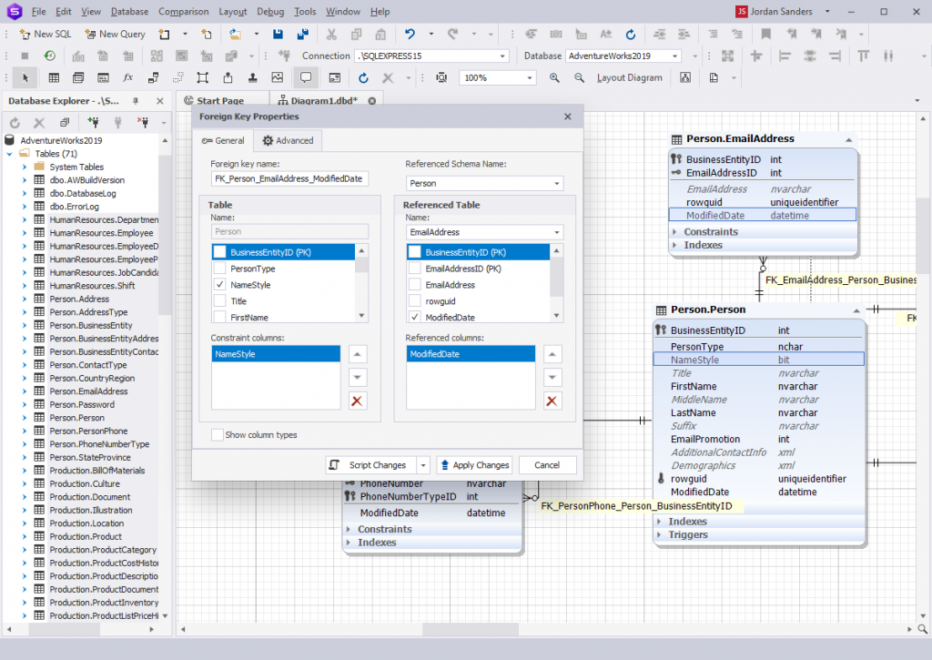
To create a new relationship:
1. Click the New Relation button on the Diagram toolbar.
2. Click the child table and move the mouse pointer, holding the mouse button pressed, to the parent table. Then release the mouse button.
3. In the Foreign Key Properties dialog that appears, provide the necessary settings and click Apply Changes.
Modify database objects on the diagram
To edit a database object, double-click it on the diagram. An object editor dialog will appear. Make the necessary changes in the editor and click Apply Changes to save them.
The View editor looks as follows:
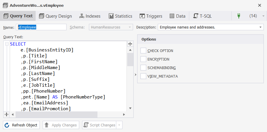
Table Designer
Table Designer comes as part of the SQL Designer functionality of dbForge Studio for SQL Server. It comprises a visual table editor that allows you to quickly and easily add columns and manage their attributes, create comments and constraints, define indexes, set triggers, work with data, preview changes, and automatically generate SQL scripts based on these changes.
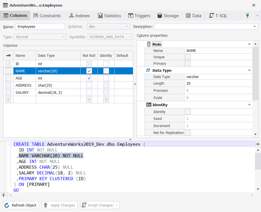
To save your changes, click Apply Changes.
Tasks that can be done via Table Designer
Tune the design of a database diagram
With dbForge Studio for SQL Server, you can tune the design of the database diagram with a rich set of options. Options can be set either globally for all the diagrams or individually for a particular diagram.
To set options for the current diagram, right-click it and select Options from the context menu that appears. In the Options dialog, you can configure the settings for the current diagram. You can also reset all the options to default values by clicking Reset.
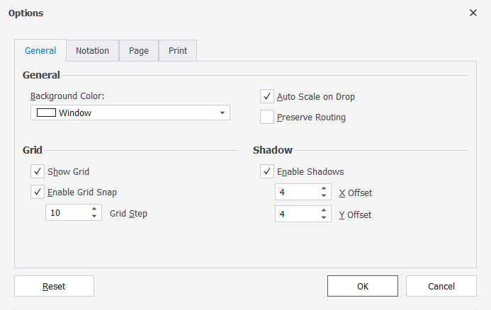
On the General tab of the Options dialog, you can adjust the diagram appearance: change the background color, select to show the grid, enable shadows, etc. On the Notation tab, you can select the skin. dbForge Studio for SQL Server supports three predefined skins: the Default skin, the Simple skin, and the IDEF1X skin. The Default skin uses the richest color palette. The Simple skin is optimized for printing and does not use gradients. The IDEF1X skin is mostly black-and-white to look like IDEF1X diagrams. On the Page and Print tabs, you can set diagram printing options.
Export SQL relationship diagram
To export a diagram to an image, follow these steps:
How to export large diagrams
When trying to export a large diagram in dbForge Studio for SQL Server, you might encounter the following error: The error occurred while diagram exporting. Probably the image is oversized. Try export to another format.
Why does this happen? The bitmap-generating engine needs a contiguous memory area for the bitmap. Even if you have enough memory, you might still get this kind of error because of memory fragmentation.
To get around the error:
Features of dbForge Database Diagram Designer
Database Diagram Visualization Tools
With dbForge Database Diagram Tool, you can customize diagram visualization to fit your needs. Keep in mind that you can choose between two common data modeling notations:
Relation comments. You can either enable or disable the rendering of foreign key names near the relation child ends.
Document outline window displays a logical structure of the currently open SQL diagram. You can use it to navigate between tables and their relations on a database diagram.
Other visualization options. You can hide constraints, indexes, and triggers compartments, and change their field detail level to display only column names, names with types, or names with full types.
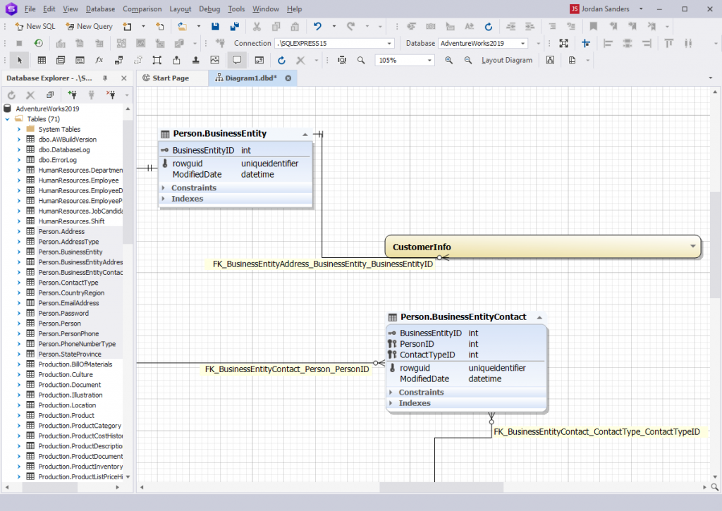
Clustering logically related objects using containers
When you work with a large SQL database diagram, a container allows you to store logically related objects in one place. You can create a new container, add the related tables, rename the container, and then collapse it.
Containers offer a logical packaging mechanism to clarify the structure of complex diagrams and are ideal for those working with large databases.
Tracking logical relations between tables
Virtual relations
Thinking of a tool that would give you a comprehensive overview of your database at any given moment & help you manage it? Explore the list of the top 7 SQL database viewer tools to consider!
Virtual relation manager contains a list of the existing virtual relations and enables you to:
Printing a database diagram
Page options allow you to set the following page settings:
Display print markup displays the print markup grid. Gray stripes show the page overlapping, which can be adjusted.
Print options allow you to:
Creating and editing database objects on a diagram
To access the Creating and editing relations option, right-click the line between two entities in the diagram area and perform the following tasks:
Creating and editing objects. You can create new database objects or edit the existing ones in the diagram area. All the changes you have made to an object on a diagram are permanent and stored on the server.
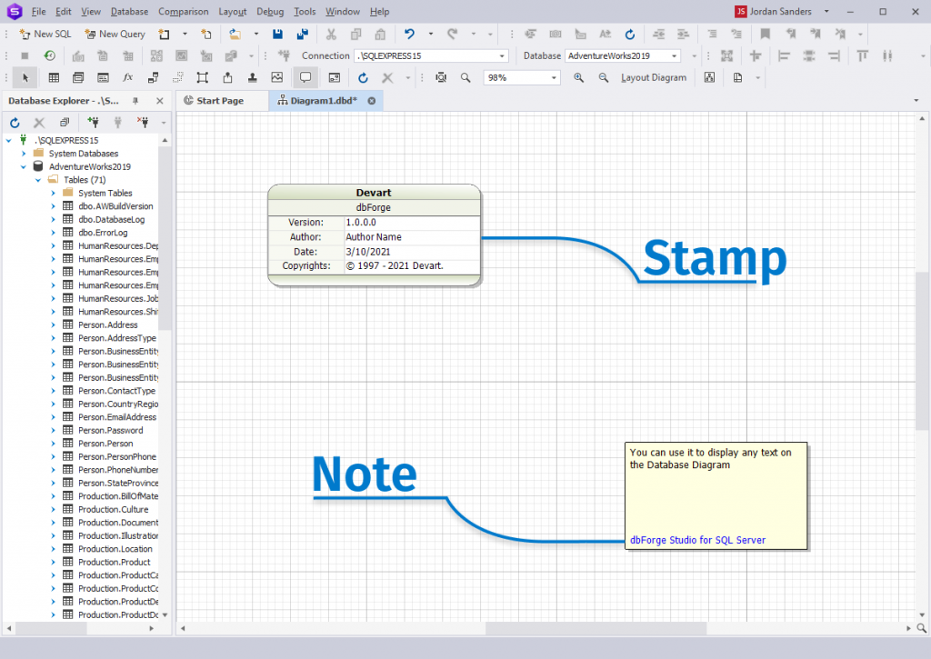
The Note feature allows you to add comments to the diagram area while designing or analyzing a database structure. You can also add hyperlinks to other resources inside your note. For instance, a hyperlink to wiki pages with database documentation.
The Stamp feature displays information about a database diagram and serves to identify a printed copy of the document.
The Adding an arbitrary image to a diagram feature allows you to add additional visual information to the diagram area, such as a diagram sketch, or draft.
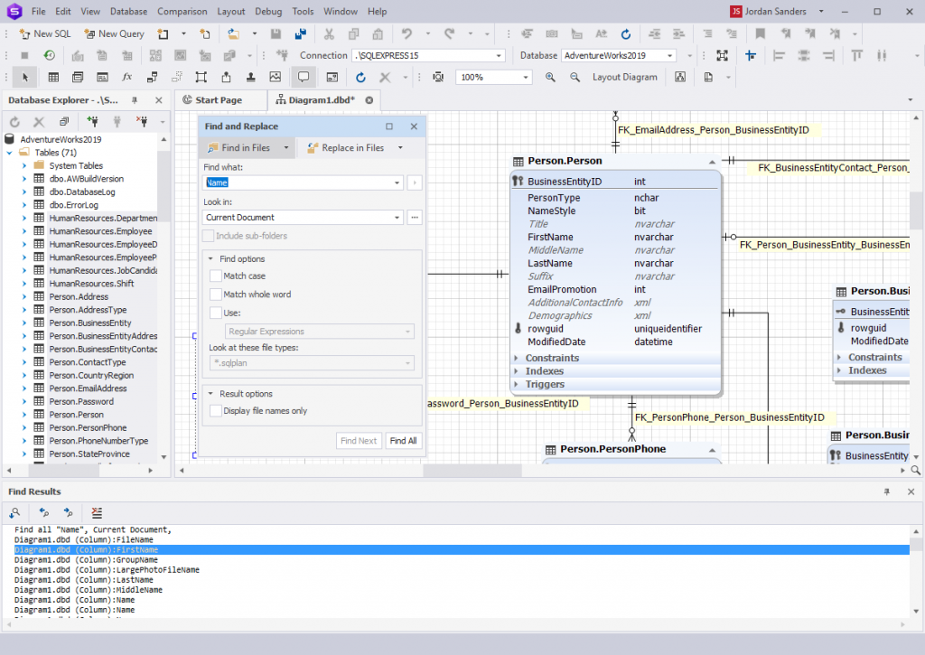
Searching text on the Database Diagram
dbForge Database Diagram Designer supports searching database object shapes by text, by their names, and names of their elements (columns, constraints, stored routine parameters, etc.). Search can also be performed in the stamp company name and project name fields, notes, relation comments, and container names.
Using additional diagram elements
Notes. Notes are yellow boxes with the text you can add to the diagram to explain some diagram parts. Notes can be moved, brought to front or sent to back, or resized like any other shapes on the diagram.
Hyperlinks. The note allows adding a hyperlink to a file if required.
Stamps. Diagram stamp enables you to specify the following information about the diagram: diagram author, company, version, copyrights, project name, and date. You can add as many stamps to your diagram as you want.
Images. dbForge Studio allows adding images to your database relationship diagram. Images can be moved, brought to the front, sent to the back, or resized like any other shapes on the diagram. You can use the following image formats:
Using reverse engineering to create database models from existing databases
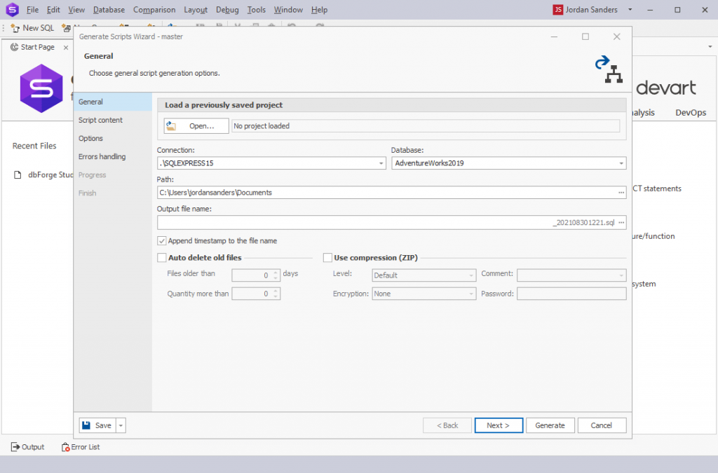
With dbForge Studio for SQL Server, you can easily export database schemas. Invoke the Generate Scripts Wizard from the Database menu > Tasks > Generate Scripts. After setting the required connection and database, specify the path and file name for the output, set up a few other options, and click Generate to launch the generation.
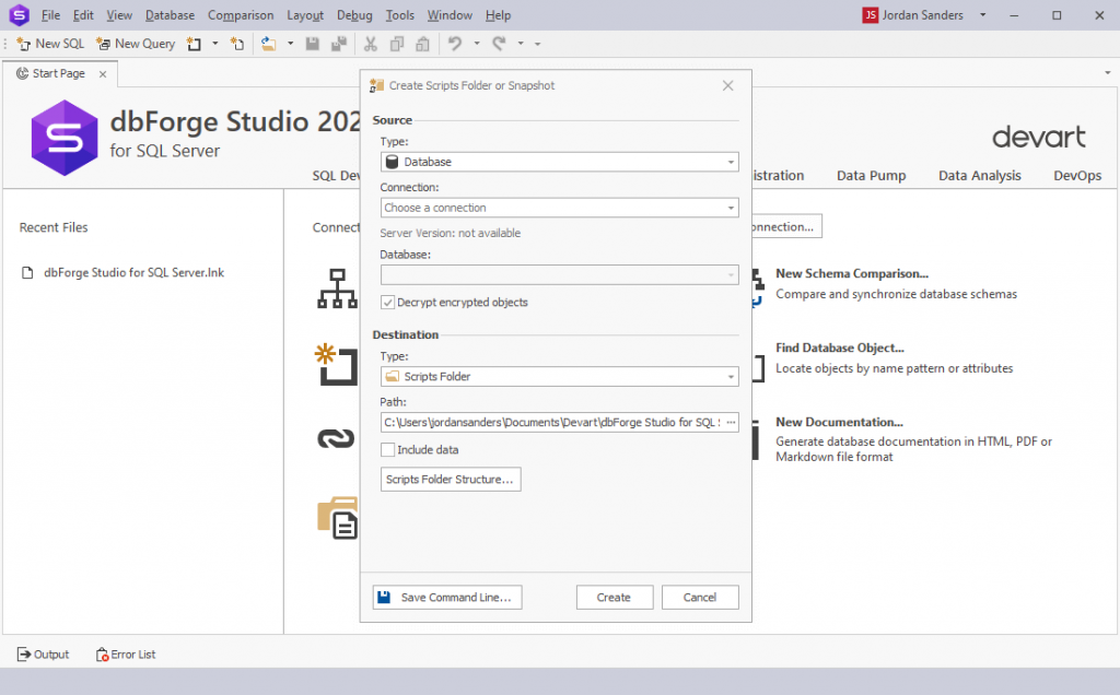
You can also create a scripts folder or a snapshot using the Studio. The former is a set of scripts that represent your database schema. The latter is a file that contains information about the structure of your database in XML. Invoke the Create Scripts Folder or Snapshot dialog box from the Database menu > Tasks > Create Scripts Folder or Snapshot. Select the required source type (database or snapshot) and specify the connection and the database (or the path to your snapshot). Along with a couple of auxiliary configurations, you set the path to store your scripts folder/snapshot file and click Create to launch the generation.
For your convenience, the generation of scripts folders and snapshots can be automated via the command-line interface using the Save Command Line button.
Using forwarded engineering to create a database from a database model
dbForge Studio for SQL Server allows you to create a database from a database model with the help of forwarded engineering. First of all, you need to create an empty database. For this navigate to Database > New Database. Enter the database name in the Name field and choose the required owner from the Owner drop-down menu. If required, type the description. Click Apply Changes.
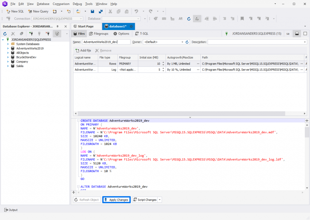
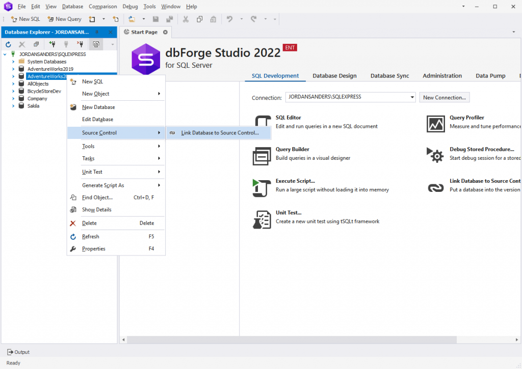
You will see the created database after you click Refresh. To link the database to Source Control, right-click it and navigate to Source Control > Link Database to Source Control:
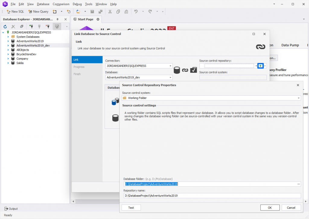
Then click the plus icon in the Source control repository field and select the folder you have generated with the Create Scripts Folder or Snapshot option in the previous step:
Click OK and select the necessary database development mode. Click Link and you should see the objects for forwarded engineering in Source Control:
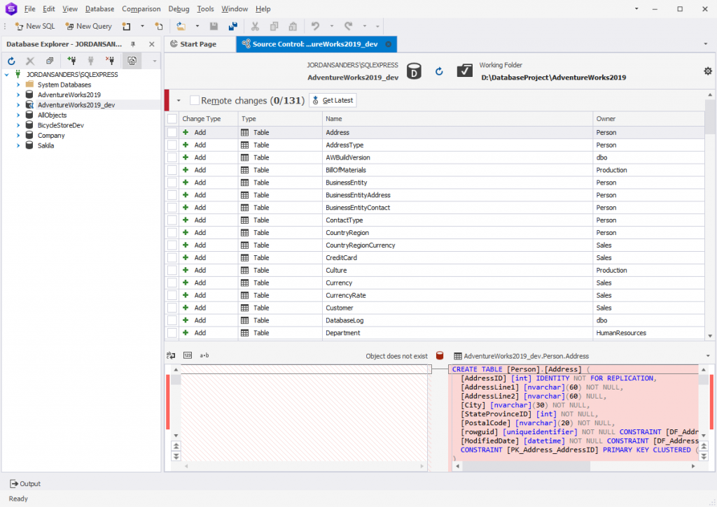
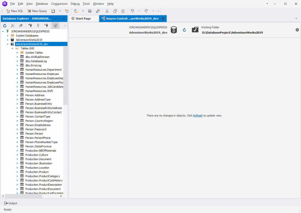
To populate the created database with these objects, just select Remote changes and click Get Latest. All data will be added to the table:
Conclusion
Grasping a database model can be quite a daunting task. It is not a problem when the database is small—in this case, it is pretty easy to comprehend how tables reference each other. However, as the database gets larger, it is often difficult to see exactly how the tables are interrelated. That’s where a good diagramming tool can come to assistance. We invite you to download and test-drive dbForge Studio for SQL Server—the IDE that will definitely exceed your expectations. We grant a free 30-day trial to potential customers so that you could evaluate the tool and fully understand its features and ease of handling.